Installation
Warning
The instructions on Safety related to the rc_viscore stereo camera must be read and understood prior to installation.
Mounting
The rc_viscore stereo camera is intended to be mounted on a wall or ceiling above the target area. It is not intended to be used in dynamic applications mounted to a robot wrist. It is the customer’s responsibility to provide an adequate mounting bracket.
For mounting, the rc_viscore stereo camera provides an M4 and M5 thread pattern on its top and bottom sides (see Fig. 7). A medium-strength thread-locker or Tuflok® screws must be used to protect against vibrations. M5 screws must be tightened to 4.0 Nm, M4 screws must be tightened to 3.3 Nm.
Warning
The rc_viscore stereo camera cannot be mounted on the end-effector of a robot.
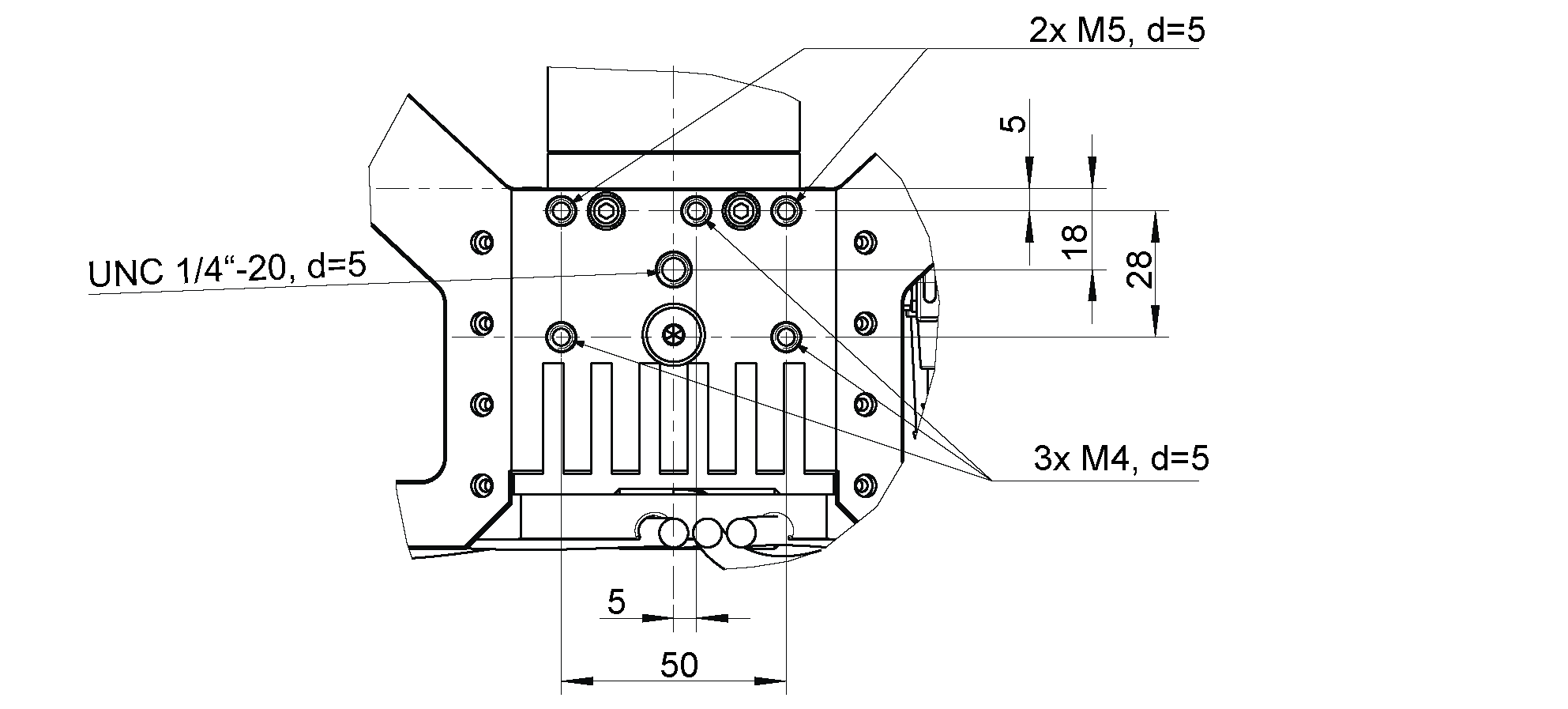
Fig. 7 Mounting of the rc_viscore stereo camera
Only the surface containing the thread pattern must be in contact with the mounting bracket, all other surfaces must remain free. At least 10 cm clearance must be provided behind the rc_viscore stereo camera to facilitate adequate air flow for cooling.
Power-up
Note
Always fully connect and tighten all M12 connectors on the rc_viscore stereo camera before turning on the power supply.
After connecting the system to power, the LED on the front of the rc_viscore stereo camera should immediately illuminate.
Warning
Do not look into the projector lens in the center of the rc_viscore stereo camera or into the light beam at any point during startup or operation.
Connecting
The rc_viscore stereo camera can be used together with an rc_cube or as a stand-alone high-resolution RGBD camera with the SGM®producer. The following sections describe connecting the rc_viscore stereo camera in both scenarios.
Connecting to the rc_cube
The rc_cube I (Industrial Edge Computer) offers four network ports that are labelled sensors 0-3. The two network cables of the rc_viscore stereo camera must be connected directly to two of those ports. It does not matter which ones. Two stereo cameras can be connected and used at the same time.
The rc_cube S (Edge Computer) offers one 2.5 gigabit sensor port. A switch must be used for connecting an rc_viscore stereo camera. The switch must support 2.5 gigabit for the connection to the rc_cube and 1 gigabit speed for the connection to the rc_viscore stereo camera. The switch is not in the scope of the delivery of the rc_cube S. Roboception can recommend a suitable switch upon request.
By default, the rc_cube is configured to support one rc_visard as sensor. For
supporting one rc_viscore stereo camera, the type of the camera pipeline must be changed in
the Web GUI of the rc_cube under
(see https://doc.rc-cube.com/latest/en/pipelines.html). Clicking on
Configure Camera Pipelines opens a dialog that permits to change
the type of pipeline to rc_viscore. A reboot is necessary after changing the
pipeline configuration.
For connecting two stereo cameras at the same time, it is additionally necessary to configure a second pipeline, as explained above, and to specify which pipeline should use which rc_viscore stereo camera by setting a filter expression. This is done by clicking on Configure Camera Connection on the Camera Pipelines page, or select the corresponding pipeline in the menu, e.g. under . Clicking Choose Camera opens a dialog to edit the device filter (see also https://doc.rc-cube.com/latest/en/pipelines.html#configuration-of-connected-cameras).
It may take up to one minute until the rc_viscore stereo camera is connected. For each successfully connected sensor, the connection speed and frame rate is shown in the of the Web GUI.
Connecting to the SGM®Producer
For using the rc_viscore stereo camera as high-resolution RGBD camera, Roboception offers the SGM®Producer, which is a GenICam compatible transport layer (see https://roboception.com/product/sgmproducer).
The producer can be used with Halcon, with the rc_genicam_api for C++ programmers, with the rc_genicam_driver for ROS and ROS2, as well as with any other GenICam compatible application. It can be downloaded free of charge from https://www.roboception.com/download and installed on Windows and Ubuntu computers with an Nvidia graphics card.
It is strongly recommended to connect both network cables directly to 1 gigabit Ethernet ports of the computer. When using a network switch, the network link between the switch and the computer should have a bandwidth of more than 2 gigabit, e.g. 2.5, 5 or 10 gigabit. Otherwise, the full frame rate cannot be reached.
In the default network configuration and according to the GigE Vision® standard, the rc_viscore stereo camera will try to obtain its configuration from a DHCP server and fall back to the Link-Local self-configuration protocol, if no DHCP server can be found. For direct connection without a DHCP server, the Ethernet ports of the computer should be configured for Link-Local network. It is also possible to manually configure IP addresses of the left and right camera.
Options for changing the network settings and IP configuration are:
- any configuration tool compatible with GigE Vision® 2.0, or Roboception’s command-line tool
gc_config. Typically, these tools scan for all available GigE Vision® devices on the network. All rc_viscore stereo camera devices can be uniquely identified by their serial number, which is printed on the device.- temporarily changing the network configuration via Roboception’s
rcdiscover-guitool. The individual cameras can be seen in the list after unchecking the Only Roboception devices check box.
Note
The command-line tool gc_config is part of Roboception’s open-source
convenience layer rc_genicam_api, which can be downloaded free of charge
for Windows and Linux from https://www.roboception.com/download.
For adjusting the focus, checking and calibrating the rc_viscore stereo camera, as explained in the next sections, the SGM®Producer package contains a calibration program, called rc_calib, and a viewer program, called rc_viewer.
Adjust camera focus
It is highly recommended to check the focus of the rc_viscore stereo camera for the actual working range. By default, Roboception focuses the rc_viscore stereo camera to a distance of 1.6 m (unless otherwise specified by the customer), which results in a working range of approximately 1.4-2.0 m. If a different working range is used in the application, the focus must be adapted. Please note that the focus range is limited due to the high resolution of the camera. At close distance, the focus range is much smaller than at higher distances. Therefore, the minimum distance for focusing should be chosen as far away as useful for the application.
If focus adjustment is needed, the lens caps of the left and right cameras must be removed as shown in Fig. 8.
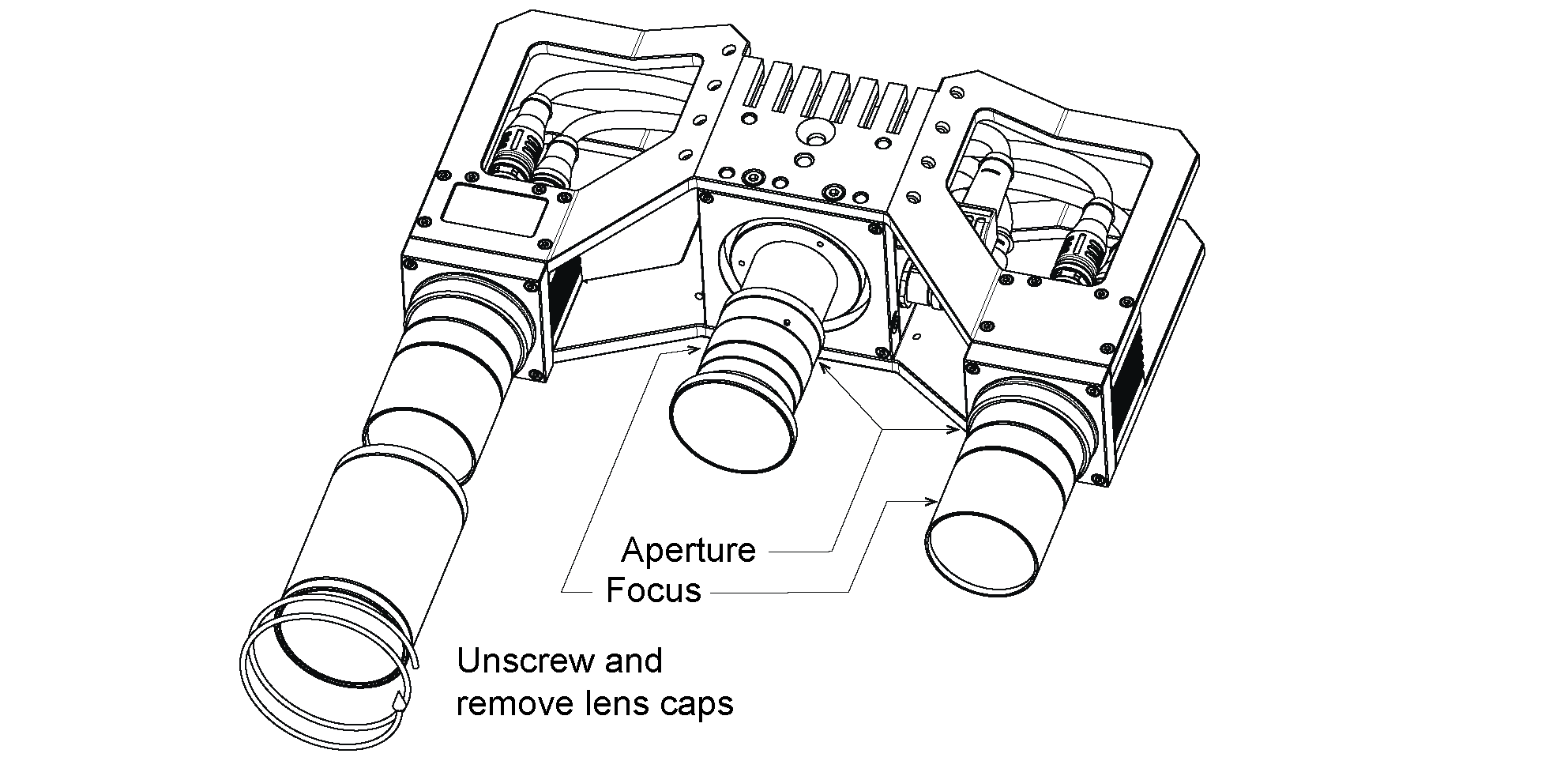
Fig. 8 Removing of lens caps for re-focusing and changing aperture
The focus ring and the aperture ring (iris ring) are locked by 3 screws for each ring as shown in Fig. 9. All three screws must be loosened for moving a ring.
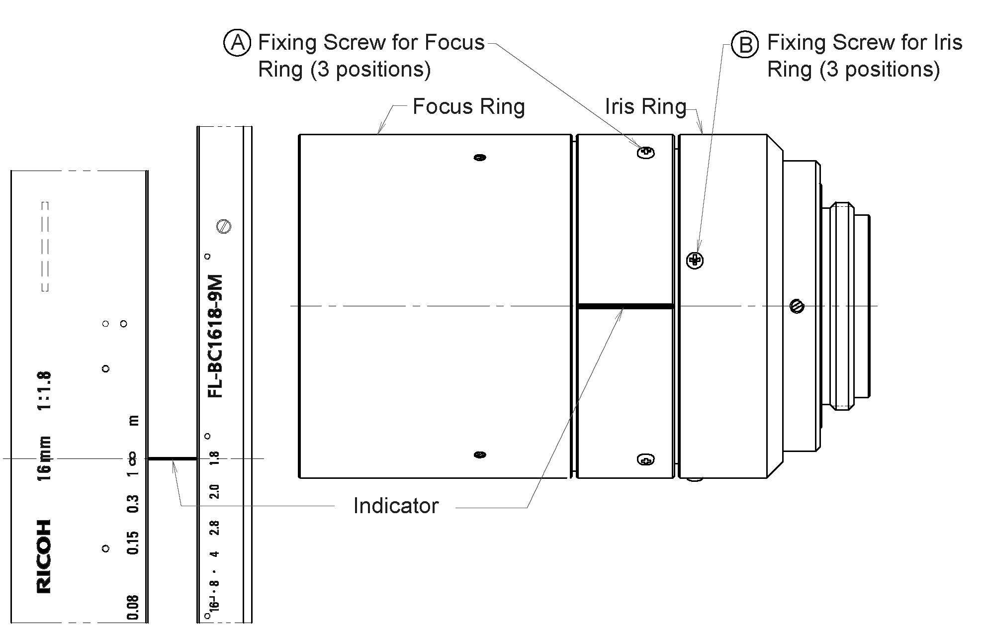
Fig. 9 Locations of screws for focus ring and aperture ring (iris ring)
The rc_cube offers a focus helper as part of camera calibration on the Web GUI under . In the first step, the size of the calibration grid has to be specified. Clicking on Next opens the focus helper. See also https://doc.rc-cube.com/latest/en/camera_calibration.html.
In the SGM®Producer, a focus helper can be found in the calibration program rc_calib after selecting the rc_viscore stereo camera with , and specifying the grid size.
The bars on the right side of the focus helper image report the blur of the calibration grid, thus a minimum is desirable. See also https://doc.rc-cube.com/latest/en/camera_calibration.html#adjust-focus.
For setting the focus correctly, the calibration grid should be placed in the middle of the working range. Then, the focus ring of each camera should be turned until the bar in the corresponding image becomes minimal. A value near the lowest dividing line is desirable. After focusing in this way, the grid should be placed at the minimum and maximum working distance. If the blur is unsatisfactory at the minimum and maximum working distance (e.g. near the second dividing line or higher), the aperture of the camera can be closed a bit by turning the iris ring, i.e. a higher aperture number should be chosen to expand the focus range of the cameras. Please be aware that this also increases exposure time and potentially gain, which increases noise in the image. The optimal tradeoff is application dependent. The default aperture number of the cameras is 4.
Warning
The same aperture setting must be used for the left and right camera to avoid degraded image processing performance. Please validate that the left and right images appear with the same brightness.
After adjusting focus and aperture, all screws must be lightly tightened and the lens caps must be re-attached.
Warning
It is mandatory to always check calibration after changing the focus or aperture of the rc_viscore stereo camera (see Calibration) .
Please contact support in case of questions regarding working distance and focusing of the rc_viscore stereo camera.
Adjust projector focus
During production, the focus of the projector is adjusted to match the focus distance of the cameras, which is 1.6 m by default (unless otherwise specified by the customer). Perfectly focusing the projector is not crucial. A slightly blurred projection pattern will not degrade the depth image.
To inspect the sharpness of the projector pattern, the projector should be turned on permanently
by setting the Out1 / Projector mode to High on the rc_cube Web GUI under
or .
The projector focus only needs to be adjusted when the projector pattern is strongly blurred. In this case, loosen the three small fixing Phillips screws on the focus ring of the projector lens as shown in Fig. 9. Then, turn the focus ring until the visible projector pattern becomes sharp. After that, lightly tighten the focus ring screws again.
Adjust projector aperture
The aperture of the projector influences the brightness of the projector pattern. By default, the aperture of the projector is fully open, which means the projector has maximum brightness. The aperture should be adjusted so that the brightness difference between images taken with projector and images taken without projector is not too large, but the projector pattern is still visible in the images taken with projector. To find the correct setting, make sure the external light in the working environment is similar to what is expected during productive mode and the rc_viscore stereo camera is mounted at the desired distance from the scene.
Then, on the rc_cube Web GUI under , set the
Exposure mode to Auto and set the Auto Exposure Mode to AdaptiveOut1.
Also set the Out1 / Projector mode to ExposureAlternateActive under IOControl Settings,
so that every second image is taken with projector pattern.
Now, the text line under the live images shows the Out1 reduction value in percent.
The Out1 reduction value describes the reduction of the brightness of the image without projection compared to the image with projection. The value should be between 10% and 20%. A higher Out1 reduction value means, that the projector is too bright compared to the external lighting, which leads to images without projector patterns being too dark. Thus, external lighting should be increased, e.g. by installing an additional light source, or the brightness of the projector should be reduced by slightly closing the aperture. In analogy, if the Out1 reduction value is too low, the projector is not bright enough compared to the external light, which means that the projector pattern will hardly be visible in the camera images and cannot enhance the depth computation. So the external light should be reduced or the projector brightness must be increased by opening the aperture.
The aperture of the projector can be adjusted by loosening the three small fixing Phillips screws on the iris ring of the projector lens as shown in Fig. 9. Then, turn the iris ring until the Out1 reduction value is in the range between 10% and 20%.
After that, the darkest object that is possible in the application should be placed in the field of view of the camera. If the dark object is not properly visible in the depth image, then the projector brightness must be increased, despite high Out1 reduction values.
In the end, lightly tighten the iris ring screws again.
Please contact support in case of questions regarding adjusting the projector of the rc_viscore stereo camera.
Calibration
After checking and potentially adjusting the focus of the cameras, the next step is to check the camera calibration. This step should never be skipped and – as opposed to all rc_visard products – is mandatory. Please note that the working range of the rc_viscore stereo camera is pre-defined and the calibration should be checked for the minimum and maximum working distance. Please contact support in case of questions regarding working distance and calibration of the rc_viscore stereo camera.
The rc_cube manual explains checking calibration and re-calibrating in detail (see https://doc.rc-cube.com/latest/en/camera_calibration.html#verify-calibration). The procedure that is described there can be applied in the same way to the SGM®Producer, by using the rc_calib program that is provided with the producer.
Warning
It is mandatory to always check calibration after mounting the rc_viscore stereo camera, changing the focus or aperture.
Recalibration is only necessary if the reported calibration error is above 0.3 pixels. After recalibration, also a new hand-eye calibration is required.
Note
Roboception will deliver the rc_viscore stereo camera with pre-adjusted focus to make sure it works in the desired depth range. Please contact support and provide your specification to enable us to set up the rc_viscore stereo camera accordingly. An onsite calibration check is still required to make sure that no problem occurred during shipping or mounting.